Comsol simulations
COSMOL simulations
Andrew's report on precession chamber design
Hg window design
Introduction
The n2EDM experiment requires using a mercury co-magnotometer to monitor the magnetic field in the same volume as the UCN. This allows for a compensation in the magnetic field drift over time and greatly improve the precession of the measurement. Mercury was chosen for a co-magnotometer because the sensitivity to its EDM is measured to be < -2.20 × 10⁻³⁰ ecm, which is 4 orders of magnitude better than that measured for the neutron.
Mercury has a vapour pressure of 1.6 × 10⁻³ torr at room temperature which makes it very convenient to optically pump. In order to optically pump mercury is requires that only odd isotope is used. Even isotopes have a completely diamagnetic ground state, no electronic spin angular momentum or nuclear spin (J = 0, I = 0).
Two of the most common isotopes are 199Hg and 201Hg, both have paramagnetism with nuclear spin I = 1/2, I = 3/2 respectively. By optically pumping these two isotopes, one obtains a purely nuclear orientation of the vapour. The mercury spectrum contains two resonance lines in the ultraviolet region, the 61 S0 - 63 P1 transition at 253.7 nm and 61 S0 - 61 P1 transition at 185.0 nm. This second transition cannot propagate in free space, this is due to very strong absorption by oxygen which is converted to ozone. The 253.7 nm is less rapidly absorbed, therefore, it is used as the optical pumping of the mercury co-magnotometer. The 253.7 nm transition of 199Hg has a hyperfine (F = 1/2) component, which is used in this case. In order to generate this excitation light a source is required, laser or lamp. Originally the nEDM experiment used a 204Hg lamp which would produce a board spectrum of UV light, containing a small fraction of the 253.7 nm excitation light. These lamps where unreliable and inconsistent, with each bulb hand made, making each one have different behaviour. In 2014-2015 this was replaced with a laser tuned to this wavelength.
The UV light is guided from the source to the precession chamber with the help of a light guide. Between the source and the chamber is a polariser and a λ/4 plate. As the light exits the light guide, it passes through a window in the precession chamber, which contains the 199Hg volume, the light is absorbed by a precessing mercury atoms and re-emitted, to be detected by a PMT sensitive to the UV range.
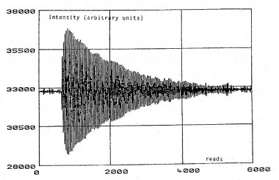
The precession chamber has a magnetic field, B0, applied perpendicular to the direction of the laser light. Before passing the excitation light, a polarising field parallel to the laser light direction, Bp is applied. After a given time, the mercury freely precess in the B0 field, with Larmor precession frequency. The subsequent signal will result in a oscillating signal with an exponentially decreasing envelop related to the wall relaxation time, T1 , and pumping time, T2, shown in the following equation:
[math]\displaystyle{ \frac{1}{\tau} = \frac{1}{T_1} + \frac{1}{T_2} }[/math]
An example of the Hg signal would look like the following:
The signal from the mercury can determine the averaged magnetic field sampled by both the UCN and mercury. This can be determined by calculating the B0 field with the following:
[math]\displaystyle{ B_0 = \frac{2 \pi f_0}{\gamma_Hg}, }[/math]
where γHg is the Larmor precession frequency of Hg.
COMSOL simulations of the window (2D)
In the case of the n2EDM experiment, the insulator ring which is used to store the UCN is made out of Rexolite. This material blocks UV light, therefore, a window is required. The geometry and surface of this window has constraints due to UCN, Hg, and HV requirements. The importance for Hg is the UV transmission of the window. The material of choice, which was used previously in the nEDM experiment is quartz. This material is chosen as it has a low Fermi potential to store UCN but high transmission of UV light.
COMSOL simulations have been performed to determine the material geometry and choice of size for this window, how will it affect the electric fields inside and outside the UCN volume. This must be checked to make sure the addition of the window will not result in high field regions which could limit the applied HV.
The quartz window needs to be held in the Rexolite insulator ring. In order to hold the window in the ring, it needs to be fixed by some holder. The geometry of the quartz window and the holder is characterized in our simulations by the following parameters:
- thickness of the quartz window
- thickness of the Rexolite holders
- curvature of the edges of the Rexolite holder
- position of the window with respect to the central axis of the insulator
- effect of gaps between the window/holder and the insulator
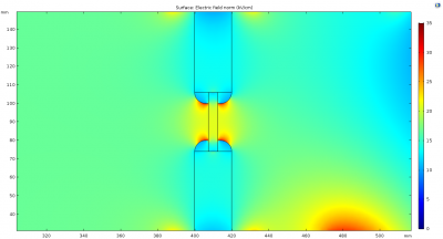
To start with, a basic design idea was implemented. The insulator ring is machined with a step on the inside to hold the quartz window against. Then a holding ring is pushed in from the outside of the insulator ring to force the quartz window perpendicular with respect to the direction of the laser light. The COMSOL simulation of this design is shown below.
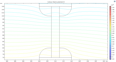
Shown is the electric field as a colour gradient and separately the potential lines. All the following simulations are done with a +200 kV potential on central electrode and ground on the top electrode. The precession chamber geometry used, is determined by Andrew (see his report above). The dielectric constant of the Rexolite is set to 3.2 (acrylic plastic) and the quartz to 4.2, are the default material properties used in COMSOL. It should be noted that Rexolite has a dielectric constant of 2.53. At the time of making the simulations the defaults were used for convenience, however, the dielectric constant of acrylic plastic being close to that of Rexolite means that the simulation will not be too far off even if the lower number was used.
This initial design has a 6 mm curvature on the inside edge of the window holder, with a 5 mm thick disc of quartz in the middle. There is a step machined into the insulator surface from the outside, so the quartz can be fixed to, the outside ring forms the holder. The window is installed by putting the quartz into the insulator ring then pushing in tight the Rexolite holder.
The simulation interestingly shows a high field is generated on the curved edge closest to the quartz window. This occurs as the potential lines in free space are focused towards the quartz window, creating field enhancements. The next step is to check what the effect of the window thickness has on the electric field in this region.
The following simulations show the same geometry with the 6 mm curvature but the quartz window thickness is changed to 2.5 mm and 1 mm respectively. In this case the potential lines are imposed on top.
It can be seen that as the window gets thinner the electric field is enhanced. This shows that as the window gets thinner it acts to focus the potential lines through the gap in the Rexolite insulator ring. This seems physical as the presence of a dielectric should displace the potential lines away, so if there is less material there, its easier for them to pass through. Therefore, one conclusion that can be drawn, is that the window should be as thick as possible.
Next the effect of offsetting the position with respect to the middle of the UCN chamber can be checked. The following is where the initial design shown previously is taken but then displaced 30 mm towards the top electrode (ground).
Its not clear in this simulation that the field are different, as can be seen in the maximum field values summarised below, there is a different from the top and bottom of the window of close to 6% of the electric field. However, the quality of the meshing could have something to do with this difference. The meshing for these simulations was set to extra fine, therefore, its possible that something else is influencing the field, such as the HV electrode and ground rings proximity.
An analysis performed with the previous nEDM experiment showed evidence that leakage current would occur primarily in the positive polarity, which could imply the offset window has something to do with this. A more detailed look of this effect can be seen here: nEDM leakage current systematic analysis. The conclusion of this analysis shows that it would be safer to place the window through the centre of the insulator ring.
At one point during the concept design of the Hg window, it was looked into the idea of using diamond instead of quartz for the window. Diamond has better UCN properties then quartz. The dielectric constant of diamond is 5-10, which can be twice that of quartz. This effect was also looked into, setting the dielectric constant of the window to 9.
Whats really interesting about this simulation is that the higher the dielectric constant, the more it displaced the potential field lines through the Rexolite insulator, thus lowering the field at the entrance of the window. In doing so this increases the field inside the Rexolite which is acceptable as the inside of the insulator has a higher dielectric strength then in the medium around it. However, diamond has a much lower UV light transmission through it, and at 5 mm would completely block the excitation light, making it not a viable option.
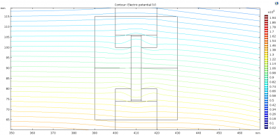
In the initial design, the curvature of the edges for the holder maybe causing the field enhancements close to the quartz window. This effect can be seen in the simulation above showing the potential field lines. Therefore, checking the effect of removing this radius at these edges was also checked, and produced the following.
To note: looking at the electric fields and the potential lines show a more gagged pattern compared with previous simulations. This could be due to a lower mesh quality here which occurs with more simplistic geometry, even with a extra fine global mesh setting. This would be a concern to validate the values but the fields found in this simulation are similar compared with the 3D versions shown below (flush ring geometry) <1kV/cm difference. The 3D simulations have a much more complex curvature, meaning the mesh is finer, which can validate the 2D simulation results.
The simulations show that the field is improved. The reason for this is that the extra Rexolite material causes the potential lines to enter it from free space first before getting closer to the quartz window. This seems to create a better transition into the quartz. Therefore, the conclusion here is that it would be better to maximise the material at these edges.
One problem with this design is that the window requires to be removed, this can lead to voids between the removable part and the insulator ring. This is inevitable as if it was a perfect fit then the two parts would never be able to separate. The previous simulations are all performed with a perfect fit, this is nonphysical, so the effect of adding gaps between surfaces was also looked at. Normally components can be machined to micron accuracy, but trying to simulate that in COMSOL will not work as the mesh would be so fine it would not be able to solve it. In order to show the effect on a compatible scale, the gap was made to be about 0.5 mm, small enough to solve but also demonstrate issues that these gap create. The simulations for this where performed at a time in which the problem with the UV light transmission of diamond was unknown so it was taken as the most optimal scenario, dielectric constant of 9 is used for the window.
As can be seen the presence of a gap can have a dramatic increase in the electric field in these regions. However, its much worse in the case where the window holder has the gap. These simulations highlight how important it will be to ensure that no voids are present once this window is installed. On a side note there are a number of ways to fill such voids. Naturally the solution is to fill these regions with something of similar electrical properties. One such method is to glue the items together, using non-magnetic stycast 1266. This would remove any voids and keep the UCN chamber vacuum tight, however, it this does fix the window in place. In order to do the same but keep the ability to remove it, the use of PTFE tape or vacuum grease is also an option. PTFE tape is less reliable to completely fill the voids and makes it mechanically difficult to press the window in place. However, grease is better as its viscous so will flow into the voids. The issue with using grease is the out-gassing effects, therefore, choice and amount of grease applied needs to be considered.
In order to quantify the simulations above, the maximum electric field in given regions need to be defined. Below is a graphic showing the regions used. The maximum electric field for each geometric condition above is summarised and presented in this excel document:
File:Field vaules determined for different window geometry.xlsx
Example of the region closest to the HV electrode, where the maximum electric field is taken is shown in blue.
As a final check to understand how the electric field is manipulated in the window region, extending the thickness of the window holders was checked. This would mean that the holders will extend pass the inside and outside radius of the insulator ring. The simulation below shows the case where the thickness of the window holders extend 5 mm inside and outside of the insulator ring radius.
Interestingly the field is the lowest of all the previous simulations. However, it should be noted that the window dielectric constant is 9. The reason that this occurs is the holders 'pushes' out the potential lines from entering the window sooner, so they all have to pass within the insulator ring.
In conclusion from the 2D simulations above, the most optimal geometry would involve:
- no curvature present on the edges of the window holders
- window is as thick as possible
- position of the window should be centric on the insulator ring
- the window holders should exceed the inside and outside radius of the insulator ring
- all gaps need to be filled
Keeping this in mind, a design was updated to be implemented in a 3D simulation.
COMSOL simulations of the window (3D)
The design of the window was changed to be the following:
In this design the insulator ring has a step machined from the outside in. This step has inside diameter of 20 mm (thru hole to the UCN volume) and outside diameter of 24 mm. This step will hold the quartz window that is 5 mm thick. There is another step which is designed for the window holder, again 20 mm thru hole and 32 mm outer diameter. The window holder is pressed into this step and pushed tight against the quartz to hold it in place. The gaps could be sealed with stycast or grease.
Two options needed to be simulated in 3D, one in which the window holder is flush with the insulator radius and the other where it sits 1 mm over the insulator outside radius, as measured from the centre of the window holder.
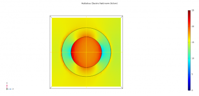
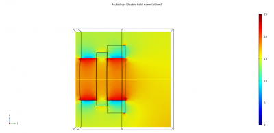
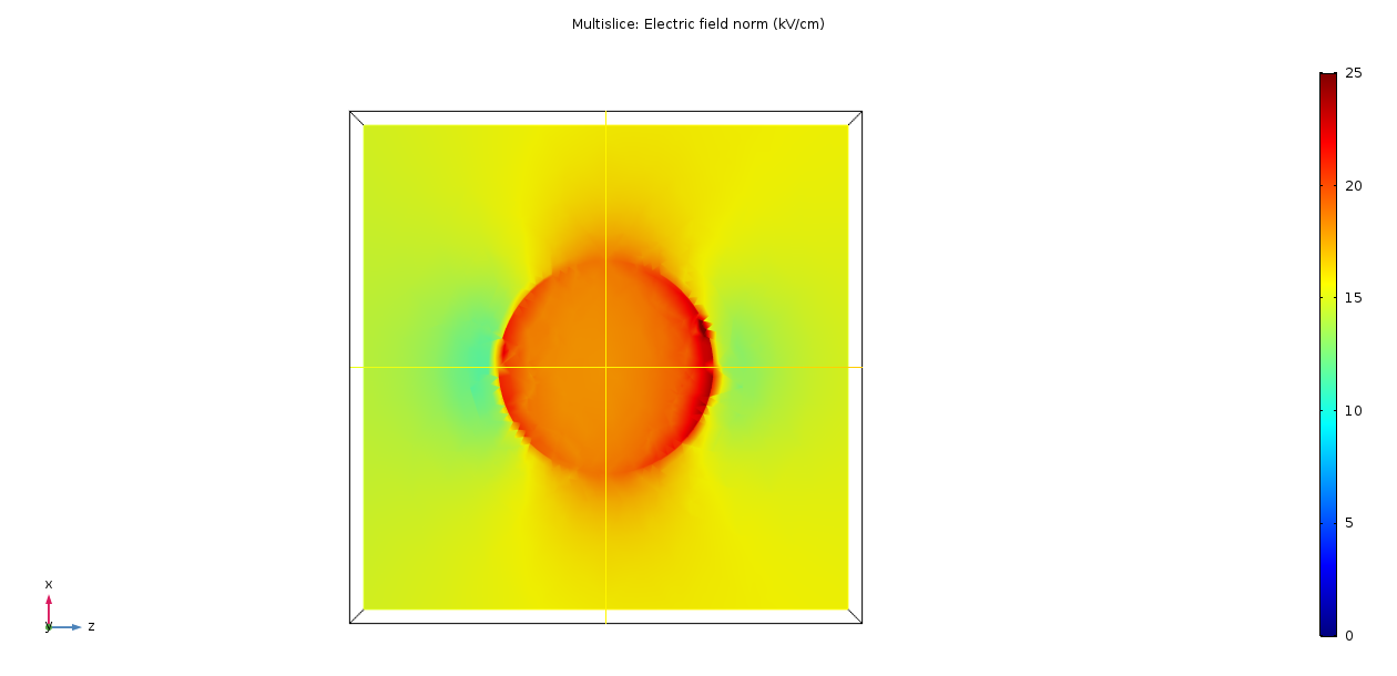
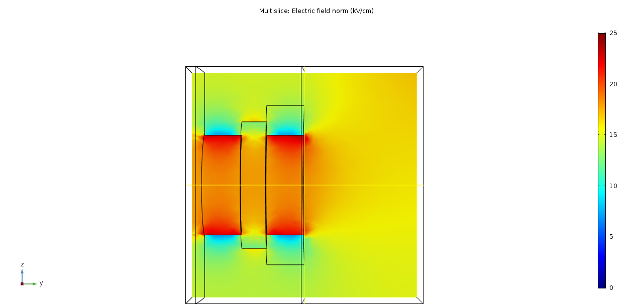
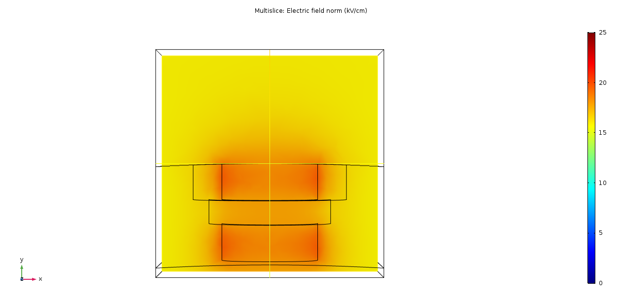
The simulations of these two options are shown below with each orientation presented.
Taking this simulation volume and scanning for the highest electric field in each gets the following result:
- Extension window: 26.5 kV/cm
- Flush window: 30.6 kV/cm
This higher field in the flush window can be seen in the front view, with the areas in red, around the inside edge of the Rexolite holder. Another interesting aspect is the high field that's generated on the edges of the extension window. This could be lowered with a radius but this would have to be small, otherwise it would return to the same problem with the 6 mm curvature on the window shown previously. It was recommended that a 0.5 mm radius is machined on to all the window holder edges.
Conclusion
In conclusion a geometry for the mercury window in the n2EDM experiment was optimised. The process of looking at changing the size and material of the window provided interesting results as to the behaviour of electric fields in varying dielectric environments. The extension window shown in the 3D simulations above was decided as the geometry for the FDR on the insulator ring for the n2EDM experiment.
References
File:Reduced limit on the permanent electric dipole moment of 199hg.pdf
File:Chibane - magnetometer thesis.pdf
https://www.engineeringtoolbox.com/relative-permittivity-d_1660.html
