Analyser Motor
Operating the analyser motor
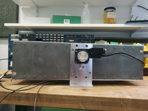
The analyser is composed of 2 sets of super mirror on top and on the bottom which are moved by 2 motors named the same way. To protect the 2 mirrors to collide and therefore be damage, 4 mechanical switch have been install to automatically stop the motor when the switch is closed.
How to plug everything:
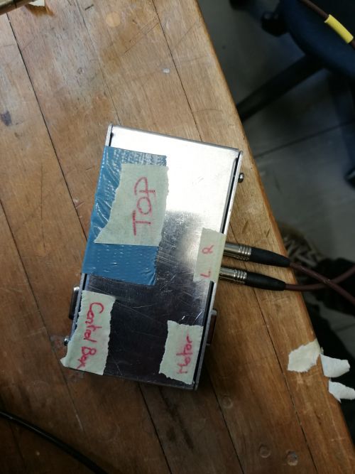
The motor with the label BOTTOM (res. TOP) is linked to the box labelled BOTTOM (res. TOP) with their own cable.
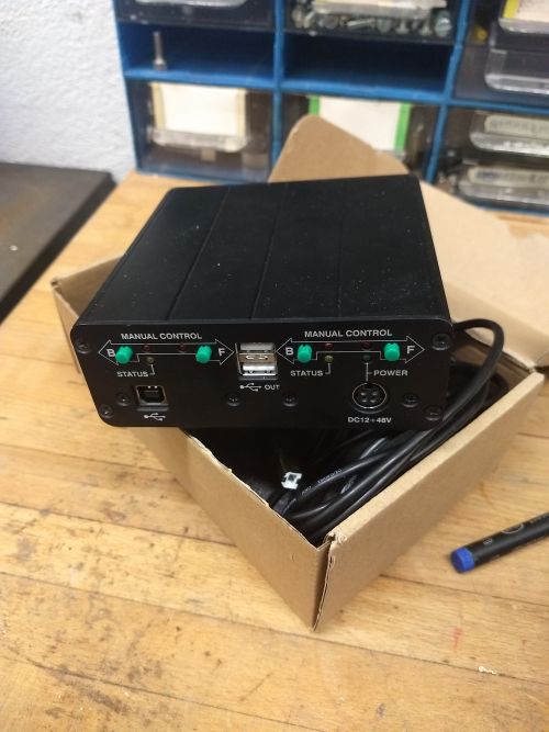
The other pseudo VGA plug labelled “CONTROL BOX” is linked to the black control box for the 2 motors via the pseudo VGA cable (axis 1 or 2, it does not matter be remember which one is which).
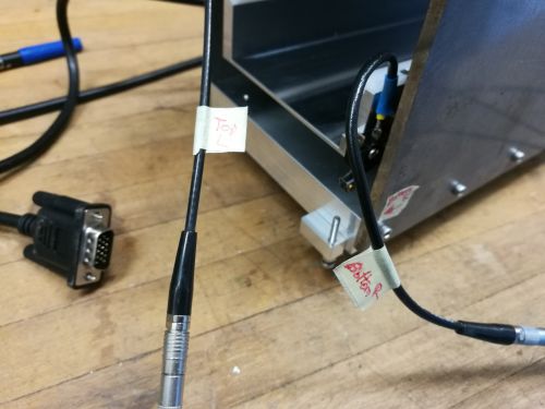
The witch labelled TOP L ( res. TOP R, BOT R, BOT L) is connected to the LEMMO plug with the same label. Plug the power cable on the “CONTROL BOX” and the USB cable to the computer with the software.
__Important:__ Make sure that the soldering is still good before using the motor. It can break.
How to use the software:
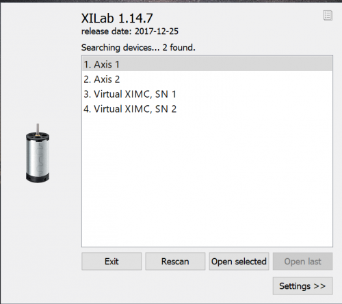
1. Search for Xilab
2. choose the motor you want to operate. There is also a simulation mode.
Important: as soon as the control box has power and is link to the computer, one can send command to the motor even if they are not plug which obviously leads to no movement for the motors.
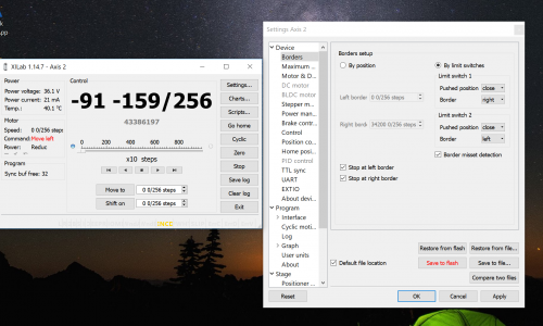
3. Clic on setting -> Device -> Borders and set the borders as in the picture below:
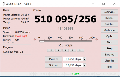
If the switch are plug in inverse, then the main window of the software become red:
